
HOW TO SETUP YOUR GRAPHICS IN REVIT
Sometimes it happens that you feel stuck while working on your graphic style, and you don’t know why you can’t set up your graphics as you would like. That’s why we want to share with you how to manage the hierarchy between:
-
- Object Style Setting
- Visibility/Graphics Override
- Phases
- Filters
- Override Graphics in View
- Silhouette Edges and Linework
Ideally, you would love to control your model entirely, but sometimes you will need to control the views with different criteria, such as by phases or by design options. Revit has many visibility settings, so we want to highlight some tips to improve your graphic style:
The FIRST THING to control is the OBJECT STYLE SETTINGS.
This is where you control the settings of the appearance of every object on your model. You can manage the properties (color, line and thickness type, etc) of every category, annotation objects, analytical models, and imported objects, and you can find them under the Manage Tab/Objects Styles.
Once you set up your objects, you can apply a type of Material and how you represent it, not only in a Graphic view but also in Renders.
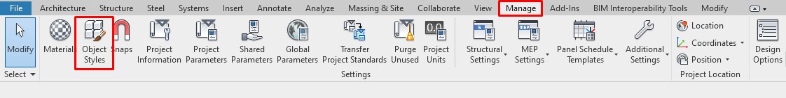
Manage/Object Styles
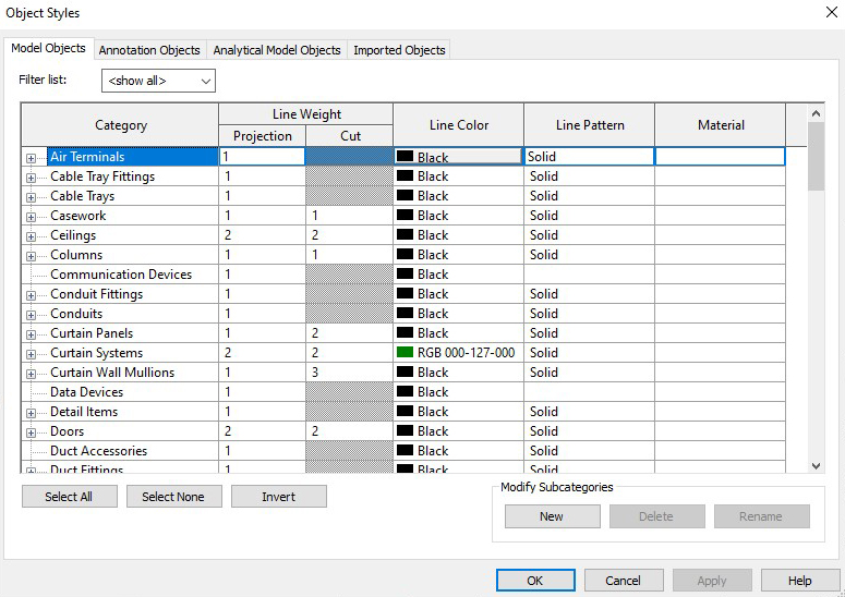
Object Styles Dialog Box
AFTER THAT, you will manage the VISIBILITY under EACH view.
Go through the Visibility and Graphics Overrides box (keyboard access: VV) under the View tab.
Once you have set your own parameters for your view, you would probably like to save it for further ones, meaning that you can (or must!) create Templates for repetitive views. For example, you can use the same type of visibility for each Elevation View, for each Floor Plan, each Detail, etc. You can create as many views or templates as you want or need to use. This is awesome, and you will save a lot of time!
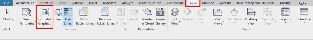
View/Visibility/Graphics
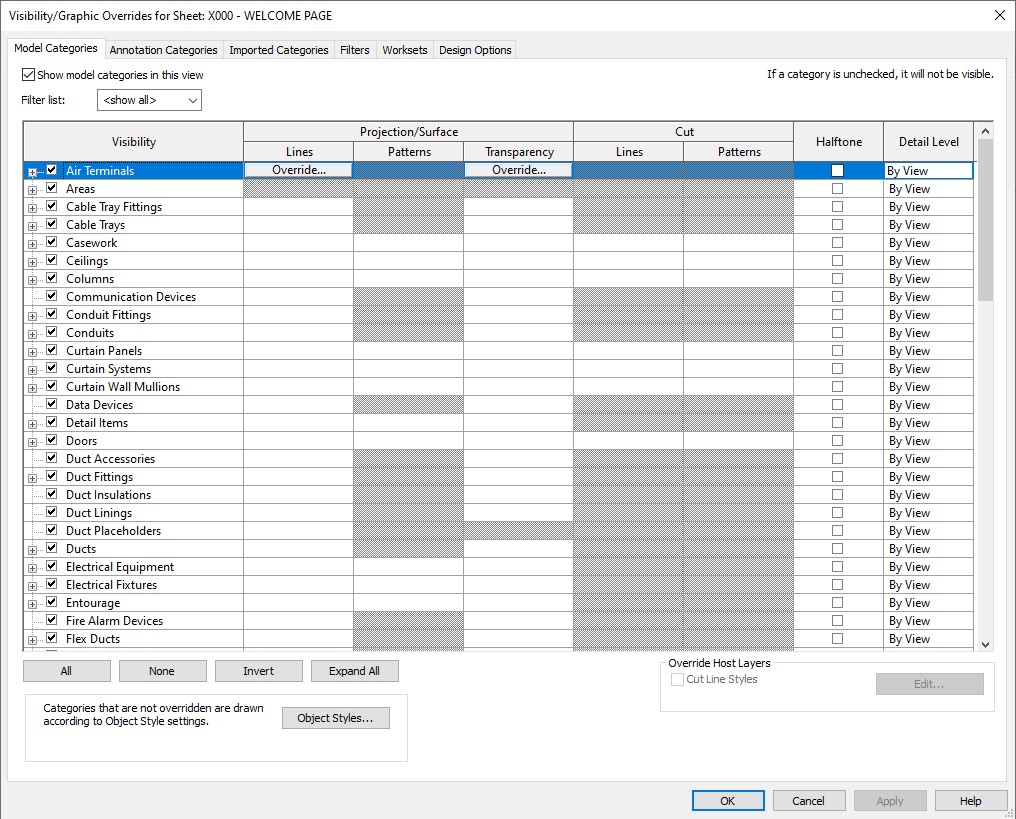
Visibility/Graphic Overrides for Sheet
Following those initial settings, you can modify your objects’ settings by using PHASES.
This is used when you have different stages on your building or construction, like a remodel or a large scale project (you will probably have New Construction, Demolition, Existing, etc.). You can find the Phases Window under the Manage Tab.
You can create as many phases as you need, and you can override their graphics as needed. For example, for walls that are planned to be demolished, you will probably want to represent them with a different hatch or color. In the sample below, the red walls are planned to be demolished, indicated by phases and with their graphics overridden.

Manage/Phases
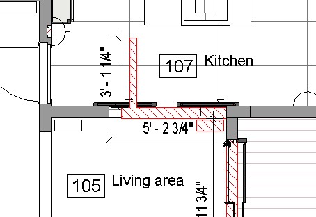
Phases Sample
Note that maybe you only have the First phase. This happens when you have a New Construction so you will control the visualization just for this one.
Next for your visual control, go to FILTERS.
You can manage your filters through the View Tab. Also, you can access them through the Visibility/Graphics Overrides Window (VV shortcut). By creating Filters, you are creating rules. In each rule, you are managing how the Graphics are shown. For example, you can set up a different color line for the Cold Water or Hot Water. The filters are applied by order. The first filter has more precedence than the Filters below. And keep in mind that every view has each Filter setting, but you always have the option to save it under a Template.
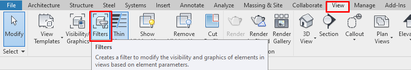
View/Filters
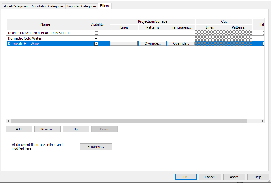
Filters Applied
Once you have all these first steps done, you may still have to render some element in a different way, in a way you couldn’t before, or maybe you just need to do something quickly.
You can use Override Graphics in View (OGV).
We do not recommend using this option for general settings, since you have to control it in every view. Think about it like a temporary setting and try to minimize this option as much as you can. To access it, select the object you want to control, and right-click with the mouse. Select Override Graphics in View/By Element/By Category/By Filter as preference.
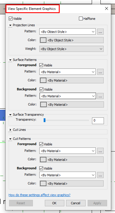
View Specific Element Graphics
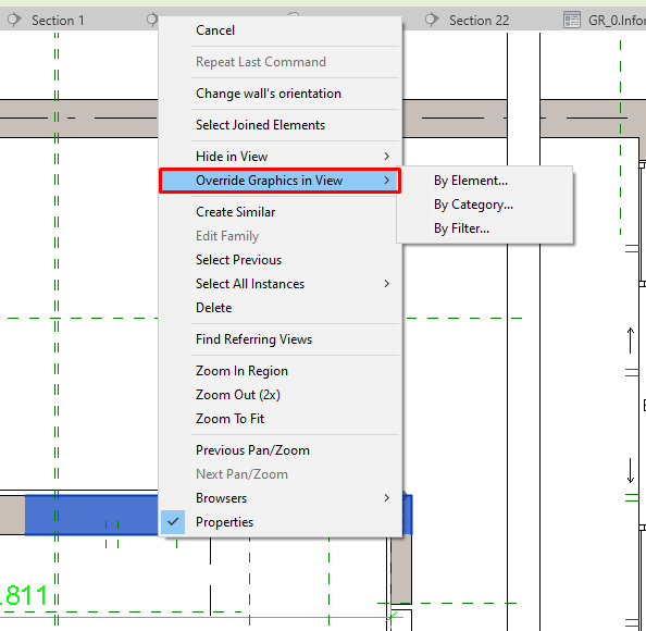
Override Graphics in View
From our perspective, Silhouette Edges together with Linework settings are used less. Like OGV, they are view-specific settings and you have to set them up, element by element. We are not saying you can’t use them, but again, try to minimize their use.
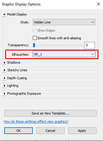
Access the Silhouette Edges settings by clicking on Graphics Display Options, and then go to the Silhouettes section. Select your line as preference.
If you go through those all options above, and you still can’t control your lines, you can use the Lineworks settings. Access them by clicking the element to be modified and click on the 3-lines-bottom on the Modify tab. Then select the line you want to apply and finally select the line.
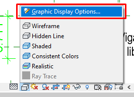
Graphics Display Options
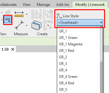
Modify Linestyle
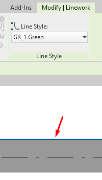
Modify Linework
Silhouettes Lines
Final Thoughts
-
- Always plan your work and project ahead. Plan how your file is going to be organized. Exchange opinions with your team.
- Work on elaborate your own start file template thinking on work you use and repeat it in every project.
- Think about what you are trying to show in each view. For example, if it is a Schematic Design plan or if you are working on Constructions Documents.
- Create templates for different types of views (plans, sections, etc) and different scales to simplify your work.
You will be an expert!